
Crude Oil Introduction

COMPOSITION OF CRUDE OIL
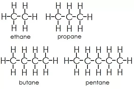
The compounds in crude petroleum oil are essentially hydrocarbons or substituted hydrocarbons in which the major elements are carbon at 85%–90% and hydrogen at 10%–14%, and the rest with non-hydrocarbon elements—sulfur (0.2%–3%), nitrogen (< 0.1–2%), oxygen (1%–1.5%), and organo-metallic compounds of nickel, vanadium, arsenic, lead, and other metals in traces (in parts per million or parts per billion concentration). Inorganic salts of magnesium chloride, sodium chlorides, and other mineral salts are also accompanied with crude oil from the well either because of water from formation or water and chemicals injected during drilling and production. 1.1.1 HYDROCARBON GROUPS Compounds solely made of carbon and hydrogen are called hydrocarbons. These hydrocarbons are grouped as paraffins, naphthenes, aromatics, and olefins. Crude oil contains these hydrocarbons in different proportions, except olefi ns, which are produced during processing. Paraffins are saturated hydrocarbons. A saturated hydrocarbon is a compound where all four bonds of a carbon atom are linked to four separate atoms. Examples are methane, ethane, propane, butane, pentane, hexane, with the generic molecular formula of CnH2n+2, where n is the number of carbon atoms in that compound. The homologous series of these hydrocarbons are called alkanes. The series starts with methane, which has the chemical formula CH4. Alkanes are relatively unreactive as compared to aromatics and olefins. At room temperature, alkanes are not affected by concentrated fuming sulfuric acid, concentrated alkalies, or powerful oxidising agents such as chromic acid. They carry out substitution reactions slowly with chlorine in sunlight and with bromine in the presence of a catalyst. Paraffins are available both as normal and iso-paraffi ns. Normal paraffi ns are straight chain compounds and iso-paraffins are branched compounds. Normal and iso-paraffi ns have the same formula (i.e., same number of carbon and hydrogen atoms), but they differ widely in their physical and chemical properties because of isomerism. The number of isomers of normal paraffins increases with the number of carbon atoms in the paraffin. For example, paraffi ns with carbon numbers of five, six, and eight will have iso-paraffi ns of three, fi ve, and eighteen, respectively. Iso-paraffi ns are more reactive than normal paraffins and are desirable in motor spirit. Normal paraffi ns can be converted to iso-paraffins by thermal or catalytic processes. This is known as the isomerisation reaction. Olefi ns are unsaturated hydrocarbons, i.e., the double bond is present between the two carbon atoms in the formula. The generic formula is CnH2n, and the lowest member of this homologous series is ethylene, C2H4. This series is known as alkenes. These are highly reactive and can react to themselves to mono olefins . Olefins react readily with acids, alkalies, halogens, oxidizing agents, etc. Olefi ns are not present in crude oil, but they are produced by thermal and catalytic decomposition or dehydrogenation of normal paraffi ns. Like paraffins, olefins may be straight (normal) chain or branched chain (iso-) hydrocarbons. Olefins can be determined by the bromine or iodine number in reaction with bromine or iodine. They are readily converted to diolefins in the presence of oxygen and form a gum-like substance. Olefins present in petroleum products can be removed by absorption in sulfuric acid. Naphthenes are cyclic saturated hydrocarbons with the general formula, like olefins, of CnH2n,also known as cyclo-alkanes. Since they are saturated, they are relatively inactive, like paraffins. Naphthenes are desirable compounds for the production of aromatics and good quality lube oil base stocks. Some of these are shown in. Aromatics, often called benzenes, are chemically very active as compared to other groups of hydrocarbons. Their general formula is CnH2n-6. These hydrocarbons in particular are attacked by oxygen to form organic acids. Naphthenes can be dehydrogenated to aromatics in the presence of a platinum catalyst. Lower aromatics, such as benzene, toluene, and xylenes, are good solvents and precursors for many petrochemicals. Aromatics from petroleum products can be separated by extraction with solvents such as phenol, furfurol, and diethylene glycol.

Complex Hydrocarbons
Crude oil also contains a large number of hydrocarbons that do not fall into the category of paraffins, olefins, naphthenes, or aromatics, but may be the combined group of any two or more groups of paraffi ns, naphthenes, or aromatic hydrocarbons. By joining two or more naphthene rings or combining naphthene and aromatic rings, paraffin chains with aromatic rings (alkyl-aromatics), etc., a vast array of complex hydrocarbons may be formed. Examples of these compounds are decalin, naphthalene, and diphenyl. Heavier fractions of crude oil contain these types of hydrocarbons. Multinuclear (multi ring) aromatics or polynuclear aromatics (PNA) are well known in crude oil and its residual products. PNAs are the precursors of coke, which forms due to thermal effect. These cannot be decomposed easily even by severe hydro-cracking.
Non-Hydrocarbons or Hetero-Atomic Compounds
Common hetero atoms in hydrocarbons are sulfur, oxygen, nitrogen, and metallic atoms. Sulfur compounds are present in crude oil as mercaptans, mono- and disulfides with the general formula R-SH, R-S-R1, R-S-S-R1, where R and R1 are the alkyl radicals. Mercaptans are very corrosive whereas mono- and disulfides are not. Examples of cyclic sulfur compounds are thiophenes and benzothiophene. Hydrogen sulfide (H2S) gas is associated with crude oil in dissolved form and is released when heated. H2S is corrosive at high temperatures and in the presence of moisture. Crude oil that contains large amounts of H2S is called sour crude. Sulfur present in petroleum fuel products also forms various oxides of sulfur (SOx) during combustion, which are strong environmental pollutants. H2S can be removed from gases by absorption in an amine solution. In the light distillates, sulfur may be present as H2S, mercaptans, and thiophenes, but in the heavier fractions of crude oil, 80%–90% of the sulfur is usually present in the complex ring structure of hydrocarbons. In this combination, the sulfur atom is very stable and non-reactive. As a result, sulfur from heavier petroleum cannot be removed without a destructive reaction, such as severe thermal or catalytic reactions. Nowadays, sulfur is recovered during refining and sold as a product. Sulfur also has a poisoning effect on various catalysts. Nitrogen compounds in hydrocarbons are usually found in the heavier parts of the crude oil. These are responsible for colour and colour instability and poisoning of certain catalysts. Nitrogen in petroleum fuels causes the generation of oxides of nitrogen (NOx), which are also strong pollutants of the atmosphere. Nitrogen can be eliminated from petroleum products by catalytic hydrogenation. Like sulfur, nitrogen in the heavier parts of petroleum cannot be removed without severe cracking or hydrogenation reactions. Oxygen compounds: crude oil may contain oxygen containing compounds, such as naphthenic acids, phenols, and cresols, which are responsible for corrosive activities. Oxygen also acts as a poison for many catalysts. This can be removed by catalytic hydrogenation. Excess oxygen compounds may even lead to explosion. Metallic compounds of vanadium, nickel, lead, arsenic, etc., are also found in crude oil. Vanadium and nickel are found in the form of organo-metallic compounds mostly in the heavier fractions of crude oil where the metal atoms are distributed within the compound in a complex form called porphyrins. Petroleum fuels containing these metallic compounds may damage the burners, lines, and Decalin Naphthalene.
PHYSICAL PROPERTIES OF CRUDE OIL
Crude oil is sometimes classified as paraffinic base, naphthenic base, or asp
haltic base, according
to the prevalence of the hydrocarbon groups. But various physical properties
are required in addition to these classifi cation in order to characterise a
crude oil. API gravity is expressed as the relation developed by the American Petroleum
Institute, as boiling in a certain range of temperatures. For a particular crude oil, each
boiling fraction separated has a certain average boiling point. A
characterisation factor of crude oil has been related with the average (molal
average) boiling point (TB in Rankine) of all the fractions separated and its
specifi c gravity “s”,
ORIGIN OF HYDROCARBONS

The word petroleum is derived from the Latin words for rock (petra) and oleum (oil). It is found in the form of gas and/or liquid phases in porous rock structures. Both gases and liquids are rich mixtures of organic components consisting of carbon and hydrogen and hence are known as hydrocarbons in general. Usually, these are available in the sub-surface of Earth in the porous rocks known as sedimentary basins. In the majority of the basins, gas, oil, and water coexist under pressure with methane gas at the cap and oil is sandwiched between the gas and water. Dissolved and liquifi ed gases are usually present in liquid petroleum oil. Heavy, carbon-rich or bituminous hydrocarbons are also available in the shallow depth in the shales (oil shales) or on the surface sands (tar sands). The most abundant hydrocarbon gas in nature, methane, is also available in large quantities from the coal bed (known as coal bed methane). Large quantities of methane are also available as hydrates under the sea bed in the Arctic region and are known as gas hydrates. There are many hypotheses about the origin of the formation of crude oil. To date, it is generally agreed that crude petroleum oil was formed from decaying plants and vegetables and dead animals and converted to oil by the action of high pressure and high temperature under the earth’s surface, and by the action of the biological activities of micro-organisms. Organic materials of plant or animal origin accumulate in the lowest places, usually in the crevices, low-lying land, sea bed, coral reefs, etc., and are gradually buried under the surface of Earth. Thus, huge amounts of organic matter are trapped layer after layer in the earth’s crust and rock. Rocks that bear these organic layers are called sedimentary rocks. Several kilometres below the earth’s surface, organic sediments are decayed biologically to a mass, known as kerogen, which has a very high mass of organic-to-inorganic ratio favourable for conversion to hydrocarbon. The temperature of Earth increases with depth (geothermal gradient) at the rate of approximately 30°C per kilometre. Thus, at a depth of 4–5 km, called kitchen by geologists, temperatures of 120°C–150°C exist where kerogen is converted to hydrocarbon oil under very high pressure of rocks and soil. But this conversion takes millions of years (geological time period) to complete. Methane is also formed thermogenically (i.e., thermal conversion of kerogen) along with biogenic methane already present before the formation of crude oil. Migration of oil with gas occurs within the rock layers by the pressure gradient from high to low pressure zones. The formation of crude (or crude deposit) oil has been found in the sedimentary porous rock layers trapped under the hard and impervious igneous rock layers. Crude oil and gas accumulate in the pores of the sedimentary rocky layer as shown in Figure 1.8. This formation may be found from a few kilometers (as deep as 2 km and as deep as 7 km) below the earth’s surface. The fi rst oil deposit is known as the Drake Well, discovered in the United States (near Titusville) in 1859. Some of the common terms used in petroleum exploration and production are source rock, migration, and reservoir. Sedimentary rocks are the rocky layer where organics are converted to oil and gas due to high temperature and pressure over millions of years. From the source rock, oil and gas then migrate to areas or traps that have a structure favourable for storing oil and gas. Traps are usually anticline or domed or faulted areas having oil and gas trapped in a porous rocky area covered by impermeable rock (seal or cap rocks) layers that do not allow further migration or escape to another area. Such an area that traps oil and gas is known as a reservoir or basin. A prospect of hydrocarbon deposits is declared by the geologist when the area under study satisfi es the above geological structure and conditions. The area where oil and gas are stored is known as formation. Drilling is started only in the prospect area as declared by the geologists. Oil reserves are classifi ed into three categories, namely, proven, probable, and possible reserves. Proven reserves are worth for economic exploitation. Probable reserve has a certain degree of probability (about 50%) for economic exploitation. Possible reserve has very little probability.
EXPLORATION TECHNIQUES

The selection of a drilling site is a tricky and costly affair. Though some visible evidence of a hydrocarbon source, like seepage of oil and gas from the surface, the visual appearance of surface and vegetation, the presence of oil or gas in fountains or rivers, etc., are sometimes used in locating oil and gas reserves, and many ancient oil fi elds were discovered by these events. But, today, such fortunate events are very rare and sometimes may not always be suitable for commercial exploitation. Modern exploration techniques use geophysical, geochemical, and geotechnical methods. Exploration of the surface of Earth can be useful for imaging or mapping sub-surface structures favourable for oil and gas accumulation. In the geophysical methods, gravimetric, magnetometric, seismic, radioactive, and stratigraphic studies of the surface are gathered. Chemical analysis of the surface soil and rocks are carried out by geochemical methods. Geotechnical methods, such as the mechanical properties of rocks and surface, are measured. Remote sensing from satellite is the most recent development for a low cost geological survey. Usual geophysical methods include gravimetric, magnetometric, and seismic methods. Geochemical methods employ chemical analysis of the cuttings (rock samples cut by drilling bit) and core (a narrow column of rock taken from the wall of a drilled hole) of the drilled site.
GRAVIMETRIC METHOD
Gravity of the earth’s surface varies with distance from the surface of Earth and the type of material, such as salt, water, oil, gas, or mineral matter. The measurement of a small variation of gravity or acceleration due to gravity is recorded with accuracy and the data are converted to retrieve a geological structure of the sub-surface of Earth. A gravimeter is a very sensitive instrument, usually a spring-type balance with high resolution and accuracy capable of detecting a minute variation in gravity. Porous and oil-containing rock layers and salt have lower density compared to the surrounding non-porous and hard rock layers. Thus, a gravimetric curve is acquired and analysed for the location of deposit.
MAGNETOMETRIC METHOD
Earth has its own magnetic fi eld that varies from one location to another owing to the different structural materials of rocks and also the presence of solar-charged particles received by Earth. A variation of magnetic fi eld strength is recorded by a sensitive instrument, called a magnetometer. Igneous non-porous rocks are found to be magnetic as compared to sedimentary rocks containing organic deposits. Thus, a magnetometric survey can also be used to locate oil deposits. Both the gravimetric and magnetometric methods are done simultaneously to predict a reproducible sub-surface structure. After the zone is confi rmed by gravimetric and magnetometric surveys, a seismic survey is carried out for a clear image of the sub-surface structure.

SEISMIC SURVEY
This technique uses a sonic instrument over a desired site to correctly locate the prospective basin structure. In this method, a sound signal generated by the explosion method (explorers call them m
ini-earthquakes, which
are artifi cially created by explosives) is transmitted through the earth’s
surface under study and refl ected signals are detected by geophones located at
specifi ed positions. The frequency and time of the refl ected signal varies
with the density, porosity, and the type of refl ecting surface. Various rock
deposits at different depths vary with density and porosity. Seismic refl
ection can measure this change as it travels below the surface. Computer
simulation software is used for imaging the sub-surface structure. This is
applied to all the surveys for fast and accurate prediction about the oil and
gas reserve location, well before a site is fi nally selected for drilling
operations. It is to be noted that exploration has to be deterministic, but the
availability of oil and gas is estimated based on probability

REMOTE SENSING METHOD
Solar radiation from the Earth’s surface varies in intensity and frequency depending on the sub-surface property. This observation is collected via satellite to predict the sub-surface structure. In order to image the sub-surface structure, historical geological data collected previously by gravimetric, magnetometric, and seismic surveys are used. The fi nal image is obtained by geological imaging software (GIS). However, the remote sensing method is not applicable during nighttime or places incapable of refl ecting solar radiation, like the ocean surface, which absorbs substantial amounts of solar radiation. However, extrapolation from the land surface in the vicinity of the sea can be accurately predicted, but is not applicable for the deep sea area. A radioactive or gamma-ray survey is also used in the exploration.
GEOCHEMICAL METHODS
Inorganic contents of surface or shallow cuttings or core are sampled and analysed for inorganic materials, such as salts and carbonates, which are frequently associated with hydrocarbons. Organic contents or the presence of organic matter is detected by heating a sample in a crucible and the loss of mass of the sample is an indication of the presence of organic matter. The ratio of organic mass to inorganic matter in a sample is used to ascertain the presence of hydrocarbons. Total organic carbon is defi ned as the carbon present in the organic matter in the sample which is different in inorganic carbon from carbonates. Core samples are examined for porosity, permeability, salt content, organic content, and many other physical and chemical properties.
STRATIGRAPHY
Correlations are established between wells, fossils, rock and mud properties, before and during drilling operations for the fi nal prediction, and this technique is known as stratigraphy. But it is important to remember that prediction from exploration may not be correct as far as the location and amount of deposit are concerned. It may happen that the drilling operation may not yield oil or the yield may not be suffi cient at the explored site and that the expenditure borne by this work is irrecoverable. Hence, a more accurate determination of the location and economic deposit should be done before investing money in well construction. After confi rmation from the test drilled hole, fi nal construction is carried out.
RESOURCE ESTIMATION
The oil potential of a deposit depends on the pressure and temperature of the formation, the surface tension, the density and viscosity of the oil, the porosity and permeability of the rock, and so forth. The quantum of oil and/or gas present in the reservoir pores is called oil and/or gas in place. The amount of hydrocarbon oil that can be economically produced and marketed is called reserve. The oil and gas volume/quantities can be estimated by the volumetric method.

EFFECT OF PRESSURE
At high reservoir pressure, the gas density is high and is dissolved in the liquid oil, and is thus amenable for the production of oil and gas without the aid of additional means of power for external pressurisation. In many reservoirs, methane is the major
At high reservoir pressure, the gas density is high and is dissolved in the liquid oil, and is thus amenable for the production of oil and gas without the aid of additional means of power for external pressurisation. In many reservoirs, methane is the major
constituent of gas,
which has a tendency to form hydrates with water at high pressure. Once formed,
methane hydrates are diffi cult to disperse in the well and may damage the well
piping due to abrasion. The formation of methane hydrates is also responsible
for a reduction in the oil pressure of the reservoir. Methanol may be injected
into such wells to disperse methane hydrates. With the production of oil and
gas, the pressure of the well falls with time (years), and to maintain
production, water or high pressure inert gas is injected into the surrounding
wells to maintain the pressure of the producing well. Pressure in the bottom of
the well at the formation can be measured with a remote access pressure gauge
lowered through the well piping. Figure 1.9 presents a pressure profi le, rate
of production, and water injection rate with age of the producing well. There
are four stages of production with ages. Stage 1 is the baby well, in which
production is gradually rising and reaches its maximum. Stage 2 is the young
well, which produces the oil at the maximum rate. Stage 3 is the middle-aged
well when production starts decreasing, and finally stage 4 is the old well, while production is very low and water cut is more than oil cut, it will
continue until it becomes uneconomic to continue production. However, external
pressurisation with water or inert gas should be planned from the beginning of
stage 2 to maintain maximum pressure with controlled production. Water
injection should be gradually raised to maintain the same pressure up to stage
4 to compensate for the fall in well pressure.
CONNATE WATER
Oil, gas, and water are distributed in the reservoir according to their densities. Gas is also dissolved in the oil phase. Gas occupies the upper space, followed by oil in the next layer, and water in the lower part. Water occupies the major space of the reservoir. Oil, gas, and water in the reservoir are also present in the interstices of the porous rocks simultaneously. This water in the pores is called connate or interstitial water. It is important to take account of this connate water in estimating crude oil in the reserve. The greater the amount of this water, the lower the permeability for oil. Water in the reservoir usually contains mineral salts. Improper selection of sites in the surrounding wells for injection of external water or gas to pressurise the producing well may result in more water cut in the production.
EFFECT OF TEMPERATURE
The temperature under the surface of Earth increases with depth. The rate of increase in temperature per 34 m of depth is called the geothermal gradient, which may be less than or greater than 1°C per 34 m. This may vary from well to well. The greater the thermal gradient, the more permeability of oil. Recently, attempts have been made to increase the bottom hole pressure by partial combustion of oil or injection of steam or hot gas into the surrounding wells.
EFFECT OF VISCOSITY
Reservoir crude oil is classifi ed as a viscoelastic fl uid that exerts normal stress in addition to tangential stress developed while in the fl owing condition. Thus, the fl ow behaviour of this type of fl uid cannot be directly expressed in terms of Newtonian viscosity. However, for steady state fl ow, the relation for pseudoplastic fl uid may be more applicable.
OIL FIELD DEVELOPMENT
Drilling is done to fracture and penetrate the rocky layers to reach the oil formation below the Earth’s surface. A hollow steel pipe containing the drill bit with perforations at its mouth is used for drilling. Mud fl uid is pumped through the top end of the drill pipe through a hose which moves down with the pipe as the drilling progresses. The drill pipe and the hose are suspended from the crown of a pyramidal structure called a rig. Figure 1.10 depicts a typical rig for drilling operations. A high pressure pump is employed to pump the mud solution from the mud pit through the hose such that the cuttings at the drill bit are washed out through the mouth of the drill bit and returned to the top surfa
ce through the annular
space between the drill pipe and the hole developed. Cuttings with the mud
solution are collected and separated from each other. Clarifi ed mud along with
fresh mud are pumped back to the drill pipe continuously. Mud is consumed due
to absorption and seepage through the pores and crevices of the layers.
Monitoring of the level in the mud pit is essential to assess the consumption
and generation pattern of cuttings and water. An alarming decrease in the level
indicates leakage through the layers due to seepage in crevices or channels.
While an increase in the level indicates ingress of
underground water. Samples of drill cuttings are useful for surveying and assessing the direction of the drilling operation as they carry valuable information about the layers and formation. Continuous well logging is then carried out using a modern system of data acquisition and analysis. After drilling to a depth of 30–40 ft, a steel pipe is introduced into the hole to protect the wall of the hole formed. This is called the casing string, which is then cemented to the wall of the hole by pumping a fast-setting cement solution (usually Portland cement without sand) to the annular space between the pipe casing and the wall of the hole. This casing helps prevent caving of the wall and seepage of water from the layers. The drilling arrangement with a casing pipe is shown in Figure 1.11. An additional drill pipe is then joined of suffi cient strength to withstand the various static and dynamic stresses for the increasing dead weight of piping, torsional stresses due to rotation, for upward and downward movement, abrasion from sand, fl uid friction from mud fl uid with cutting and corrosion, etc. The drilling operation is then continued and an additional casing pipe of a reduced diameter from the previous one is inserted and cemented at strategically located positions (for easy recovery of casing pipes after the well life is exhausted) until the target depth is reached. The fi nal casing diameter may reach as small as 5–8 in. At this stage, the top of the well (well head) along with the casing hanger are fi tted with the necessary piping and collection headers. A pipe riser is inserted in the well to lift the oil and is connected to the well-head piping and valves. The diameter and design of the pipe riser (tubing) may differ depending on the facility of the oil lifting mechanism. The well-head connection consists of a tubing header and a Christmas tree header for collection of oil, gas, and water to the respective storage tanks. Such a complete well is presented in Figure 1.12. The surface of the casing pipe at the desired target depth is punctured by bullet or missile fi ring by experts. The hydrostatic pressure of the mud fl uid in the well hole balances the reservoir pressure, thereby preventing spouting of the well from the formation.
WELL LOGGING
Well logging is a continuous recording process of the activities during drilling, well development, and production until the closure of the well. Thus, the record identifi es the history of the well. Well logging is carried out during the drilling operation using special probes (electrical resistivity, inductance, or magnetic resonance), physical sampling of the drilled soils and rocks, core samples, monitoring drilling fl uid, etc. Various parameters, such as porosity, permeability, and water saturation in oil, of the formation are also obtained by the resistivity probes. During the drilling operation, information about the drill bit, its movement, and direction are determined by these probes. The direction of drilling is ascertained by the dipole sharing investigation tool (DSI). Information is also gathered to release drill bits stuck in the well, monitoring the perforation operation of the casing to communicate with the formation, the properties of oil and gas in the formation, etc. At various stages of production, well probing is used to inspect the casing, the wall of the uncased well, etc., for necessary maintenance operation of the well.
OIL PRODUCTION PROCESSES
The gas lift method employs high pressure gas, usually air or carbon dioxide, which is introduced into the well through the annulus and oil is carried through the inner tubing, leading to the well-head piping. Initially, the well is fi lled with the mud fl uid and the oil cannot move up owing to the hydrostatic head of the mud fl uid. As the gas enters the annulus and piping, the density of the mud column decreases and the hydrostatic head decreases, and as a result, the mud fl uid is lifted by the oil pressure. A mud–oil mixture is collected and separated on the surface tanks. When complete displacement of mud takes place from the well and from the pores of the layer near the borehole by the oil pressure, oil production starts increasing. Such a schematic gas lift operation is shown in Figure 1.13. A sucker rod lift well contains a piston (or a plunger) pump lowered into the inner tubing. The piston is operated by a metallic wire or rod leading through the tubing and above the well head and connected to a wire rope from a hanger attached with a reciprocating driving system at the base of the well head. The piston is contained in a cylinder with non-return valves fi tted at both ends. During the upstroke of the piston, the bottom valve opens, keeping the top valve closed and, as a result, the cylinder pressure falls below the reservoir pressure, forcing oil to enter the cylinder. While during the down stroke of the piston, the upper valve opens and the bottom valve closes and oil in the cylinder is pushed up to the tubing through the upper valve. Thus, the volume of oil displaced upward in the tubing is proportional to the stroke length of the piston. When the tubing is fi lled with oil after repeating the reciprocating operation, oil starts fl owing upward and is collected. A schematic sucker rod lift arrangement is shown in Figure 1.14. A submersible pump well contains a centrifugal or screw pump installed in the tubing lowered into the borehole. Both the electric motor and the pump are submersed in the well bottom. Electric cable sealed in a fl ameproof arrangement is lowered into the well hole through the tubing. The motor is usually kept below the pump in the tubing. Pumps are small in diameter (3–6 in), multistage centrifugal or screw pumps. Since entrainment of sand particles and gas may cause problems to the centrifugal pumps, modern wells are using high capacity multistage screw pumps that can carry slurries, viscous oil, and even gas. In fact, future wells will deliver more viscous oil contaminated with sand and clay materials, therefore, increasing use of submersible screw pumps will take place in modern and existing wells. Modern screw pumps with a diameter as small as 6 in with a capacity of 100 m3 or more per day and with a head of 1000 m are being used in wells. The number of stages of a pump may be more than 100 tightly fi tted in a tubing. A submersible pumping well is shown in Figure 1.15. The hydraulic pumping method employs a special type of tubing that consists of two tubes. The inner tube is of a larger diameter in which the plunger or the diaphragm pump is lowered into the borehole. The plunger or the rod of the diaphragm is forced by pumping a liquid over it in a reciprocating manner. Oil is discharged through the outer pipe through its annular space and is delivered to the surface tank. This method does not require lowering any electrical cable and no wire for actuating the plunger. A high-pressure reciprocating surface pump delivers the liquid forced up and down the plunger of the pump in the borehole in a reciprocating manner. The plunger pump can be withdrawn on the surface from the inner pipe by forcing liquid through the annular outer pipe. Such a pumping arrangement is shown in Figure 1.16. The rate of production from a single well may not be large. Hence, a good number of wells, varying from 100 to 1,000 wells depending on the rate of production, are drilled in the area where the formation is spread. Excitation (stimulation) of the wells by gas or water injection from
the surrounding
injection wells (judiciously located) is extremely necessary to increase
reservoir pressure to the fl owing wells. Modern methods also employ combustion
of oil in the surrounding wells to push the oil in the formation by heat effect
on reducing viscosity in the porous channels of the formation. A proper
temperature gradient is essential from the channels of the combustion zone to
the target well. Crude oil from all these wells are collectively routed to
storage and conditioning
CRUDE CONDITIONING AND STORAGE

Hydrocarbon gases and light and heavy hydrocarbon liquids are all present in a single homogeneous phase under pressure in the formation before it is drilled. After this is released from the formation, components of crude oil separate into layers of light and heavy hydrocarbons. Raw crude oil collected from the wells also contains sand, mud, and water as impurities which may vary from 20% to 30% by volume. Hence, raw crude is collected in a battery of treatment tanks where both storage and treatment of crude oil are carried out. Treatment steps involve gravity settling and removal of sand and water followed by chemical treatment to remove emulsifi ed water and, fi nally, to a crude conditioning unit. Gases lighter than propane have a tendency to escape, whereas propane and heavier gases are found dissolved in crude oil at atmospheric pressure. Proper mixing and repeated heating above room temperature (usually 45°C–50°C at low pressure and up to 90°C at a pressure of 2–3 atm) followed by cooling to storage temperature can increase the dissolution of gases and homogenise the layers of light and heavy liquid hydrocarbons. Segregated wax in crude oil may choke the pipeline and pumping equipment due to deposition. Heating of crude with a mixing facility reduces segregation of wax by making it uniformly distributed in the bulk and thus it can be stored and transported without risk of deposition for many hours at room temperature or lower temperature above the pour point. Asphaltic and heavy hydrocarbons with high viscosity are also mixed up with wax and other hydrocarbon components during the heating and cooling cycle, making them less viscous. Heating can be provided by a steam coil in the storage vessel with mechanical mixers, and cooling is done in another vessel with cooling coils in which refrigerants may be the vaporizing hydrocarbon gas or other liquids. Heating and cooling vessels are connected in sequence. Conditioning of crude oil can also be done by heating and cooling in sequence in pipe coils at the required temperatures. Mixing is enhanced for high velocity in the pipe coils. This type of conditioning method reduces the cost of storage and loss of gases. Conditioning may also be used for mixing oil and gases from various wells in the desired proportion to meet the desired quality. Water and slop (oil and water mixture) from the treatment unit is also treated in the battery before recycling to wells.
TRANSPORTATION AND METERING OF CRUDE OIL

Treated crude oil is received in large storage tanks usually under pressure to avoid loss of hydrocarbon vapours and is despatched by tankers (ships), trailers (large tank cars), and most conveniently through pipelines. Pipelines as long as 1000 m or more from the oil fi eld tanks to the refi neries or to the shipping ports are most common in any oil-producing country. Booster pumping stations are placed at the required positions to maintain delivery pressure to the receiving ends.
High pressure centrifugal or screw pumps are employed
for pumping through pipelines. The horse power of such pumps may vary from 500
to 2,000 hp with a capacity to transport 500–1,000 m3/h with a discharge
pressure of 100 atm or more. Power consumption depends on the pressure loss and rate of delivery, which is ultimately determined by the viscosity of the oil,
the roughness of the surface, and the diameter and length of the pipe, fl ow
rate, etc. Injection of methane in the pipeline may be useful for boosting
pressure and this is separated from crude only at the refi nery.
However, this is not suggested for loading in a tanker or while crude contains
water, which may form abrasive methane hydrate crystals at low temperature.

Quantity loaded in the vessels of the tanker or trailer or to refi nery tankages
are measured directly by physical dipping using calibrated dip rods or tapes as
required. Flow rate through a pipeline is measured by low-pressure drop fl ow
meters to reduce power loss. Ultrasonic, electromagnetic, or tracer type fl ow
meters with signal-generating devices are suggested as these do not come in
contact with the oil and hence no pressure loss occurs. Pressure sensing gauges
are also installed at vital distances of the pipeline to monitor any failure of
pumps or oil leakage in the line. Electrical signals from the fl ow and
pressure sensors are transmitted continuously to control rooms at the
originating and booster pumping stations. Nowadays, verbal and digital
communication and recording between these stations are maintained by computers.

Private microwave towers are also built for this purpose. Since pipeline routes
are on the surface, underground, or under river or sea bed, it may be necessary
to have proper vehicles to check the pipelines for maintenance. Helicopters are
commonly employed to access remote places. Pipeline washing is carried out
using a leather or polymer ball (known as pig) pushed by pump pressure at one
end and collected at the pig-trapping-pit end before reaching the suction of
the booster pump. Pressure safety valves are located at places to release oil
or gas to prevent damage to the pipeline during excessive pressure rise owing
to blockage of the line for any reason.
GAS HYDRATES
Methane occurs naturally due to the biological decomposition of organic matter available on the earth’s surface and is frequently manifested as marsh gas from wastelands, ponds, etc. Large gas reserves under the earth have been detected where methane exists as crystals (gas hydrates) formed due to the interaction with water and methane molecules as a clathrate compound at high pressure and low temperature, usually below 20°C. Because of the abundance of methane gas formed in the geological period under the earth’s surface, usually in the Arctic region below the sea bed which is enough to saturate water at a very low temperature, methane hydrates are formed. Gas hydrates have been found at depths of 200 m to 1,000 m in the sea. Below this depth, ice layers, permafrost (permanent frost), of water is prevalent. The temperature of sea water decreases as depth increases and the rate of decreases in temperature with respect to the depth is known as hydrothermal gradient. While the geothermal temperature below the sea bed increases at a rate of 34°C per km. Thus, gas hydrates exist only a few hundred meters below the sea bed where the temperature is below 20°C and after this depth it cannot exist because of higher temperature due to geothermal conditions. Gas hydrates are lighter than water once dislodged from the bulk it fl oats on the sea water and gradually releases methane from the sea surface. Hydrates are stable up to a maximum temperature of 15°C. Hence, if the temperature increases above 15°C, gas will be released from the hydrate. In fact, other hydrocarbon gases, such as ethane, propane, butane, carbon dioxide, and helium, may also be present in the hydrates along with methane. The presence of these gases also contributes to the stability of gas hydrates in a range of temperatures. Hydrate reserves are identifi ed by the seismic exploration method. Approximately, 164 Nm3 of methane is available from 1 m3 of gas hydrate containing 0.2 m3 of gas and 0.8 m3 of water. Exploration is carried out during winter while the sub-sea level is favourable for stable gas hydrates in the reserve.
PRODUCTION METHOD
A well is drilled and hot water is introduced to release the gas. But propagation of heat through the well to the reserve will cause the release of gases from the surroundings of the well, as a result a special type of dome-shaped collecting device is
used. Methane is traced
by infrared (IR) sensor. The economics of the production is dependent on the cost of energy supply
for generating hot water by burning a part of the recovered gas and cost of
collection. The ratio of heating value of methane to the heat required to
release methane per cubic meter of hydrate is a good indication of the economic
viability of such a production method. Compressed carbon dioxide as the product
of combustion in this process is injected back into the reserve to replenish
the gas collected. Since gas hydrates are available in the deep sea area,
exploration and production require huge investments and operating expenses.
Storage of methane and its transportation are also troublesome due to gas
hydrate formation. In a pipe transfer under the sea or low temperature area,
methanol is injected to avoid hydrate formation at the prevailing temperature.
Though large amounts of gas hydrate reserve is available in the permafrost
zone, it is diffi cult to produce with the existing technology.
COAL BED METHANE
Methane is strongly adsorbed by coal and hence coal mines contain methane in the coal bed. Methane obtained from the coal bed is called coal bed methane (CBM) Hazards in coal mining are commonly encountered owing to the presence of methane, which is poisonous and explosive. Extraction of methane from the coal bed is a recent activity by the oil and gas companies. In fact, methane extraction can reduce the risk of coal mining and generate methane as a valuable fuel. However, production of methane from the coal bed is based on some fundamental rule of adsorption. Methane and carbon dioxide are usually adsorbed in the coal bed. Both gases are strongly adsorbed, in fact, carbon dioxide is more strongly adsorbed than methane. Coal bed well is usually full with water, which exerts a hydrostatic pressure over the bed resisting desorption of gases from the bed. The presence of water causes carbon dioxide to be present in the water phase due to high solubility, whereas methane remains adsorbed in the coal. According to the adsorption isotherm, the quantity of adsorbed methane increases with pressure. Thus, if pressure is reduced by dewatering, methane will be desorbed from the bed. With this theory, methane is extracted from the coal bed by dewatering through a well. Thus, methane comes out from the annular portion of the well piping.
Methane is strongly adsorbed by coal and hence coal mines contain methane in the coal bed. Methane obtained from the coal bed is called coal bed methane (CBM) Hazards in coal mining are commonly encountered owing to the presence of methane, which is poisonous and explosive. Extraction of methane from the coal bed is a recent activity by the oil and gas companies. In fact, methane extraction can reduce the risk of coal mining and generate methane as a valuable fuel. However, production of methane from the coal bed is based on some fundamental rule of adsorption. Methane and carbon dioxide are usually adsorbed in the coal bed. Both gases are strongly adsorbed, in fact, carbon dioxide is more strongly adsorbed than methane. Coal bed well is usually full with water, which exerts a hydrostatic pressure over the bed resisting desorption of gases from the bed. The presence of water causes carbon dioxide to be present in the water phase due to high solubility, whereas methane remains adsorbed in the coal. According to the adsorption isotherm, the quantity of adsorbed methane increases with pressure. Thus, if pressure is reduced by dewatering, methane will be desorbed from the bed. With this theory, methane is extracted from the coal bed by dewatering through a well. Thus, methane comes out from the annular portion of the well piping.


No comments